
Views: 0 Author: Site Editor Publish Time: 2026-08-14 Origin: Site
Matching water application rates to the fire load dictates operational success on the fireground. If you under-flow a room, the thermal layer collapses. If you over-flow it, you waste water and increase fatigue. Procurement teams and fire officers frequently face an equipment trade-off. Fixed-flow nozzles limit tactical flexibility when conditions change rapidly. Selectable flow options require strict adherence to pressure and flow calculations to prevent under-performance. Evaluating a 1.5 inch NST fire nozzle requires rigorous analysis of system pressure capabilities, application scenarios, and material durability. This guide breaks down the technical specifications, LPM conversions, and operational realities of the 30, 60, 95, and 125 GPM settings. We will look at how to align these flow rates with specific fire loads to inform smarter deployment decisions and keep nozzle operators safe.
Tactical Versatility: A selectable gallonage nozzle utilizes a rotating selection ring, allowing operators to adjust flow rates from 30 to 125 GPM to adapt instantly to changing fire conditions without shutting down the line.
Pressure Dependency: Flow settings are strictly dependent on available nozzle pressure (typically rated at a 100 PSI baseline); selecting 125 GPM on a low-pressure system will result in degraded stream reach and droplet size.
Application Specificity: Lower settings (30-60 GPM) are engineered for lower water pressure availability and residential scenarios, while higher settings (95-125 GPM) maximize high-flow systems for commercial fire loads.
Standardization: Verifying National Standard Thread (NST/NH) compatibility and NFPA 1964 compliance is mandatory. A 1.5-inch NST nozzle will only connect to a 1.5-inch NH/NST hose without specialized adapters.
Fire suppression teams require equipment that scales water delivery based on the immediate thermal threat. Swapping hose lines mid-operation wastes critical time and allows the fire to grow unchecked. A selectable gallonage nozzle solves this problem by integrating multiple flow rates into a single appliance. Operators can dial up the flow for rapid knockdown or dial it down for overhaul without ever shutting down the water supply at the pump panel.
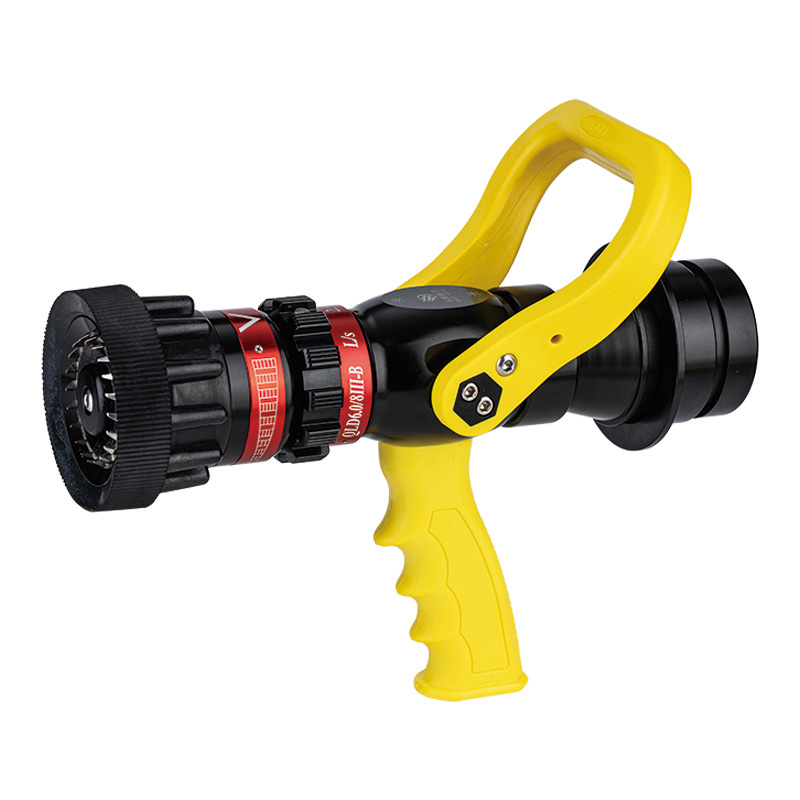
The core mechanism relies on a rotating external selection ring located just behind the bumper. This ring connects to an internal baffle and stem assembly. When an operator turns the ring, machined detents catch spring-loaded ball bearings, locking the ring into specific flow settings. This physical rotation alters the distance between the baffle and the nozzle body, changing the size of the discharge orifice. A smaller orifice restricts water flow to 30 GPM. A larger orifice opens the waterway to permit 125 GPM. The engineering goal is to regulate the flow volume while maintaining an optimal nozzle pressure, ensuring the stream shape remains effective across all four settings.
The internal components work together in a specific sequence during operation:
Shut-off Bale: The horseshoe handle controls the main water flow. Pulling it backward opens the valve; pushing it forward stops the flow.
Ball Valve: A spherical valve with a hollow center. When aligned with the waterway, water passes through. When turned perpendicular, it seals the waterway.
Selection Ring: The external dial that dictates the maximum volume of water allowed through the orifice.
Baffle and Stem: The internal components that move forward or backward based on the selection ring's position, physically restricting or opening the flow path.
Turbine Teeth: Spinning metal or composite teeth located at the bumper that break the solid stream into uniform droplets when a fog pattern is selected.
Understanding the difference between nozzle types prevents dangerous fireground errors. Automatic nozzles feature a dynamic internal spring. They maintain a constant 100 PSI pressure by automatically varying the flow based on the water supplied by the pump. Selectable nozzles operate differently. They deliver a specific, operator-chosen GPM, provided the pump delivers the rated pressure. If the pump pressure drops, the selectable nozzle will not automatically compensate. The stream will weaken, and the reach will diminish. Operators must communicate clearly with the pump operator to ensure adequate pressure matches the selected setting.
The 1.5-inch form factor remains the industry standard for interior attack lines. It offers an optimal balance between maneuverability and water delivery. A 1.5 inch handheld fire nozzle is light enough for a single firefighter to advance down narrow hallways, navigate tight stairwells, and push into cluttered residential rooms. Yet, it supports flow rates high enough to extinguish standard residential fires. Larger 2.5-inch lines deliver massive amounts of water but require multiple personnel to move and position. Smaller 1-inch lines lack the knockdown power for structural firefighting and are relegated to wildland use. The 1.5-inch profile hits the operational sweet spot for municipal and industrial response teams.
Selecting the correct flow rate dictates the speed of extinguishment. It also impacts water conservation, property damage, and operator fatigue. A 30 60 95 125 GPM nozzle provides four distinct tactical options. Each setting serves a specific operational purpose on the fireground.
The 30 GPM setting is strictly for low-intensity applications. It delivers approximately 115 liters per minute. This setting excels during mop-up operations and overhaul. Once the main body of fire is extinguished, crews must pull ceilings, open walls, and find hidden embers. High flow rates cause unnecessary water damage to the property below and disrupt fire investigation evidence. The 30 GPM setting provides a gentle, controlled stream. It is also the go-to setting for wildland applications where water is scarce. When dragging a line through the brush and running off a small skid unit with a 200-gallon tank, water conservation is paramount. In long hose lays with extreme friction loss, this setting ensures a functional stream even with low terminal pressure.
The 60 GPM setting delivers roughly 230 liters per minute. This represents the baseline for incipient stage residential fires. Think of a trash can fire that has extended to the curtains, or a single mattress burning in a bedroom. It provides sufficient cooling capacity for standard room-and-contents fire loads without flooding the compartment. A single operator can easily manage the 30 pounds of reaction force at this setting. The 60 GPM rate balances rapid heat absorption with minimal water waste. It prevents rapid steam conversion from overwhelming the compartment, which can burn the attack crew. Crews frequently use this setting for fast interior attacks in single-family dwellings where the fire is contained to the room of origin.
Stepping up to 95 GPM (approximately 360 LPM) changes the tactical dynamic. This setting tackles higher heat release rates. It is required for heavily involved residential rooms extending into hallways, small offices, or light commercial spaces. The increased water volume absorbs massive amounts of BTUs quickly, dropping the temperature of the thermal layer before flashover occurs. However, this setting introduces significant physical trade-offs. The nozzle reaction force increases sharply to nearly 50 pounds. A single operator will fatigue quickly without proper technique. Operating at 95 GPM requires a solid stance, aggressive use of the pistol grip, keeping the hose straight behind the operator for at least ten feet to absorb the kickback, and often a backup firefighter on the line.
The 125 GPM setting delivers maximum knockdown power for a 1.5-inch line. At roughly 475 liters per minute, it is designed for heavy fire conditions. Crews use this setting for defensive operations from an offensive position, such as a fully involved attached garage threatening the main living space. It is highly effective for protecting exposures or cooling large fuel loads in industrial settings. Operating at 125 GPM demands robust pump discharge pressure. It pushes the safe operational limit of a standard 1.5-inch hose line. Friction loss becomes a major factor, requiring the pump operator to throttle up significantly. The reaction force exceeds 60 pounds, mandating a two-person team for sustained operation to prevent the line from whipping out of control.
Procuring an adjustable flow fire nozzle requires looking beyond the flow rates. Thread compatibility, material science, and ergonomic design dictate the lifespan and safety of the equipment. Overlooking these dimensions leads to catastrophic failures on the fireground, putting personnel at immediate risk.
Thread mismatch is a critical failure point in fire suppression. National Standard Thread (NST) is identical to National Hose (NH) thread. An NST fire hose nozzle features a specific thread pitch and diameter designed exclusively for NST/NH couplings. A 1.5-inch NST connection typically features 9 threads per inch. You cannot mate an NST nozzle to a National Pipe Straight Hose (NPSH) or Iron Pipe Thread (IPT) coupling, which feature 11.5 threads per inch. Forcing a connection causes cross-threading. Under 100 PSI of pressure, a cross-threaded nozzle will blow off the hose line, causing severe blunt force trauma to anyone in its path. Always verify thread standards before procurement. Look for the Higbee cut on the threads—a machined notch that indicates the start of the thread, allowing for instant alignment in zero-visibility environments.
Historically, fire nozzles were cast from solid brass. Brass offers excellent durability and does not corrode easily, but it is incredibly heavy. Dragging a brass nozzle up three flights of stairs exhausts the operator before they even flow water. Modern tactics demand lighter equipment to reduce operator fatigue. An aluminum fire hose nozzle solves the weight problem. Manufacturers use heavy-duty, aircraft-grade aluminum alloys, such as 6061-T6 or 401 aluminum. To match the durability of brass, the aluminum undergoes Mil-Spec Type III hard anodizing. The metal is submerged in an acid electrolyte bath, and an electrical current creates a thick aluminum oxide layer on the surface. This layer is as hard as tool steel. It provides exceptional resistance to galvanic corrosion, deep scratches, salt water, and harsh Class A foams. Hard-anodized aluminum delivers the strength of brass at half the weight.
A high-quality nozzle must transition smoothly through various spray patterns. The bumper controls this transition. Operators need a tight straight stream for deep penetration into burning materials and maximum reach. They need a narrow fog for hydraulic ventilation, pushing smoke out of a window. They require a wide fog pattern for heat shielding and crew protection during a flashover event. The bumper must turn easily, even with heavy, wet firefighting gloves. Ergonomics also play a vital role in managing reaction force. A rugged pistol grip allows the operator to anchor the nozzle against their body, transferring the kickback into their core rather than relying solely on grip strength. The horseshoe shut-off handle (bale) must operate smoothly to prevent water hammer—a destructive shockwave caused by closing the valve too quickly.
Deploying selectable gallonage nozzles introduces specific operational risks. Improper use or poor maintenance compromises fireground safety. Departments must implement strict training and maintenance protocols to mitigate these hazards and ensure the equipment performs when lives are on the line.
The most common error on the fireground is selecting a high flow rate without adequate system pressure. If an operator selects 125 GPM, the nozzle requires 100 PSI at the tip to function correctly. The pump operator must calculate the Pump Discharge Pressure (PDP). PDP equals the Nozzle Pressure (NP) plus the Friction Loss (FL) of the hose lay, plus any elevation changes. If the pump or standpipe can only deliver 50 PSI to the tip, the stream will fail. The water will fall short of the target. The droplet size will increase, reducing the surface area available for heat absorption. Mitigation requires rigorous hydraulic training. Pump operators must calculate friction loss accurately. Nozzle operators must understand the limitations of their water supply and select a GPM setting that matches the available pressure.
Flow Rate Application and Reaction Force Summary
GPM Setting | LPM Equivalent | Primary Application | Estimated Reaction Force | Staffing Requirement |
|---|---|---|---|---|
30 GPM | ~115 LPM | Overhaul, Wildland, Mop-up | ~15 lbs | Single Operator |
60 GPM | ~230 LPM | Residential Incipient Stage | ~30 lbs | Single Operator |
95 GPM | ~360 LPM | Commercial, Heavy Fire Load | ~48 lbs | 1-2 Operators |
125 GPM | ~475 LPM | Defensive Attack, Exposures | ~63 lbs | 2 Operators Minimum |
Physics dictates that higher flow rates generate higher reaction forces. Nozzle reaction force pushes back against the operator. At 125 GPM and 100 PSI, the reaction force exceeds 60 pounds. Fighting this force while advancing a charged hose line through a structure causes rapid physical exhaustion. Fatigue leads to a loss of stream control, endangering the crew and allowing the fire to spread. To mitigate this risk, departments must establish standard operating guidelines (SOGs). Mandate a two-person team on the line for sustained operations at 95 or 125 GPM. Train crews on proper body mechanics, utilizing the hose as a counterbalance, and the effective use of the pistol grip.
Selectable nozzles contain moving parts that are susceptible to damage. Debris from hydrants, such as rust scale or rocks, can clog the internal baffle mechanism. The selection ring can bind if exposed to extreme heat or physical impact. The shut-off ball valve can degrade over time, causing leaks. Mitigation starts with procurement. Ensure the nozzle carries an NFPA 1964 certification. This standard dictates rigorous performance and durability testing for spray nozzles. Field maintenance is equally important. Crews must utilize the flush setting to clear debris after every use. Turning the ring past the highest GPM setting opens the baffle completely, allowing large debris to pass through.
Implement the following inspection steps after every fire:
Check the bale for smooth operation without binding.
Inspect the turbine teeth for missing or broken pins.
Rotate the selection ring through all detents to ensure the ball bearings click into place.
Verify the rubber gasket inside the coupling is present and pliable.
Flow test the nozzle annually to verify the GPM output matches the dial settings.
Audit your current hose inventory to confirm all threads are strictly NST/NH standard before purchasing new nozzles.
Verify the maximum flow capacities and discharge pressures of your existing pump systems or standpipes to ensure they can support 125 GPM operations.
Request certified 100 PSI flow-test data from manufacturers prior to executing bulk purchases.
Update department standard operating guidelines to dictate minimum staffing requirements for the 95 and 125 GPM settings.
Implement a mandatory post-fire maintenance protocol that includes utilizing the flush setting and inspecting the turbine teeth.
A: National Standard Thread (NST), also known as NH, features 9 threads per inch on a 1.5-inch connection. National Pipe Straight Hose (NPSH) features 11.5 threads per inch. They are entirely incompatible. Attempting to mate them causes cross-threading, severe leaks, and a high risk of the nozzle blowing off under pressure.
A: Yes, as long as the thread types match. The vast majority of 1.75-inch interior attack hoses are manufactured with 1.5-inch NST couplings. The 1.5-inch nozzle threads directly onto the 1.5-inch coupling of the 1.75-inch hose. This setup delivers higher water flow while significantly reducing friction loss in the hose lay.
A: The flush setting opens the internal baffle to its absolute maximum diameter. This creates a wide clearance that allows large debris, such as rust scale, rocks, or sediment from hydrants, to pass through the waterway without clogging the mechanism. Operators must flush the equipment after every single use.
A: A weak stream at 125 GPM directly indicates insufficient nozzle pressure. Selectable nozzles require a specific baseline pressure, typically 100 PSI at the tip, to function correctly. If the pump operator does not throttle up to overcome hose friction loss and deliver that 100 PSI, the stream will severely degrade.
A: Yes. Mil-Spec Type III hard anodizing creates a thick aluminum oxide layer on the surface of the metal. This layer is incredibly hard and highly resistant to galvanic corrosion, deep scratches, and chemical degradation. It provides the rugged durability of traditional brass but at a fraction of the weight.
A: For a straight or solid stream, the standard fireground formula for nozzle reaction is NR = 0.0505 x Q x √P, where Q is the total flow in gallons per minute (GPM) and P is the nozzle pressure in PSI. This calculation helps officers determine the required staffing for the hose line.


